Speaking with a coworker the other day it dawned on me that there are a number of areas of networking that just aren’t covered as part of the ‘normal’ course of learning. Things like IGPs,EGPs, spanning tree, FHRPs, and access lists are covered in depth and can be found everywhere from books to blogs to week long training classes. Then there’s ‘the other stuff’ – Best practices for cabling, UPS design, monitoring, scripting, and power and cooling, just to name a few. The stuff that isn’t documented as well but is still an absolute necessity for most people at some point in their network engineering career. In the next few blog posts I’m going to run through the basic design process for the power and cooling of your switches.
Power Basics
Before we can jump into determining the power requirements for your switch we need to gain a basic understanding of how power is calculated. The formula to calculate power is P = VI, or spelled out: Power = Voltage x Current. Power is measured in watts, usually abbreviated by W, Voltage measured in volts abbreviated by V, and Current is measured in Amps, abbreviated by A.
A common analogy that is often used to explain each of the terms is that of a garden hose or plumbing system. In this analogy the Voltage is equivalent to the pressure in the system, the Current is equivalent to the rate of flow, and the Wattage is the total amount of water that comes out of the hose or pipe. Let’s say you need to fill up a swimming pool using the hose. We can turn the water on using the normal faucet and it will fill slowly (low pressure), or if we used some type of external pump we could fill the pool quickly (high pressure). Similarly, if the network switch we are working with needs more watts(maybe you have PoE line cards with attached phones you need to power), we can increase the voltage which will generate more watts. For more details on the basic power formula or the water analogy check out this site.
Calculating Power Requirements
At some point in buying the new switch you’ll need to provide the power requirements to someone like an Electrician to make sure you have enough power to run the switch. Every linecard, supervisor, and PoE device you put into your switch will have some power draw and you need to make sure you have enough power available. If you’re working with a switch in the Cisco Catalyst(and Nexus 7K) line, they have a very useful tool called the Cisco Power Calculator (Free,CCO Login Required) that lets you build your switch with specific linecards and will output the power and cooling requirements. Let’s take a look.
After you launch the tool you select the product family from the dropdown.

After selecting the product family, you start to populate the switch with the specific chassis model, supervisor, redundant supervisor if applicable, and input voltage. For input voltage, we have four choices. The first two choices, -48 Volts DC and -60 Volts DC are used if you’ll be connecting this directly to a battery as the source. DC voltage is popular for phone system/telecom equipment as it doesn’t introduce noise (audible hum) into the line like AC would, and provides assurance against power outages. Bonus fact: The DC voltage is negative to reduce corrosion. The second two options in the dropdown are 100 – 120 Volts and 200 – 240 Volts. Every deployment of a Cisco switch I’ve done so far has used AC power to supply the switch, either straight from a wall outlet or outputted from a UPS, and the example I’ll run through will use AC voltage. How do you know which AC voltage you should pick? There are a couple factors:
- Country you are deploying the switch in. Some countries have a standard voltage of 100-120 Volts and some countries have a standard of 200-240 Volts. Find out what voltage is standard in the country the switch will be installed and choose accordingly. Note that these are the standard voltages, but there may be other options (for example, while 110 Volts is common in houses in the US, it is not uncommon to have 220V circuits installed in offices, datacenters, or other locations that may need additional power). Work with your electrician.
- Existing electrical wiring or new electrical wiring. If you are installing this switch and need to utilize the existing outlets or UPS, you can work with the electrician or building management to determine what voltage you have available to you. If it is a brand new install and you have the ability to tell the electrician what to install, then you can run through the Cisco Power calculator using both voltages (if available in your country) and see which works better for you.
For this example I’m going to select 200-240 Volts, as that’s what I’ve typically worked with for the bigger chassis based switches with multiple linecards. I also selected redundant Sup720s.

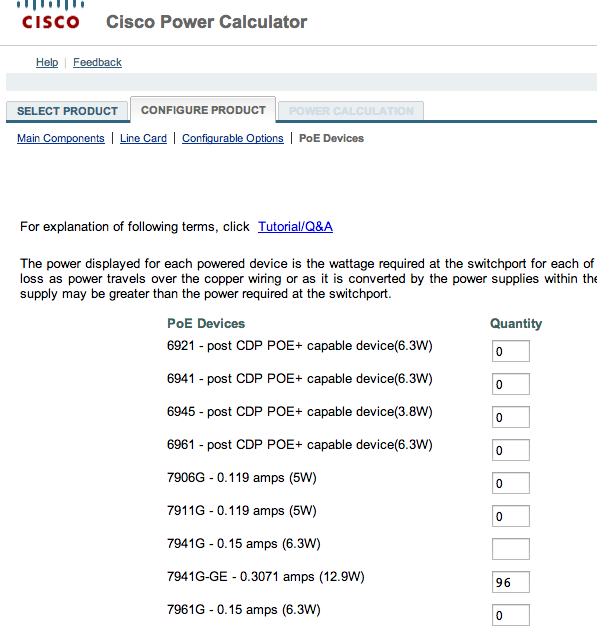
On the next page you can select which linecard will go in each slot. If you select a PoE linecard it will ask you to specify the number and type of PoE devices attached to that linecard. It’s important to keep in mind what your future growth may look like. For example, if you only will have two PoE linecards today, each partially filled with some PoE devices, you may be able to get away with a small power supply and a lower voltage circuit from your electrician today. If you know that you will be expanding sometime in the near future, it’s much easier to get the bigger power supply and have your electrician wire the electrical circuit appropriately now, then need to revisit this in 6 months or a year when the electrician needs to install all new circuits and you need to buy bigger power supplies. Each situation will be different so there is no one size fits all, use your judgement.
I’m going to populate this chassis with 4 PoE linecards and tell the wizard that I’ll be connecting 96 Cisco 7941-G-GE phones. The calculator knows the power draw for every PoE device(phones, access points, etc) in the list so you just need to know how many of each you have now (or will have in the future) and give it some good estimate.
Now we’re ready to look at the results. There’s a lot going on in this page but it’s not that bad if you break it down. The top sections show you how you’ve configured your switch and the MINIMUM power supply and number of power inputs you could get away with to adequately power this switch and connected devices. It’s important to note the number of inputs. Most of the bigger power supplies may offer the option for multiple inputs. This is good in that it allows you to supply more power to the switch, but you’ll need to keep in mind that for every additional input into the power supply it means an additional circuit/outlet that your electrician will need to install if this is a new install, or that you would need to already have available if it will be utilizing existing outlets. The “Percentage Used” section with colored meter will show you what percent of the listed power supply you will be using from the start. You typically would want to include room for growth. In my example, if we chose the minimum power 8700 Watt power supply with a single 220 Volt input, we would already be at 96% utilization. If I’m asked to install an additional line card a few months from now, we will need additional power, most likely in the form of an additional electrical circuit/input.
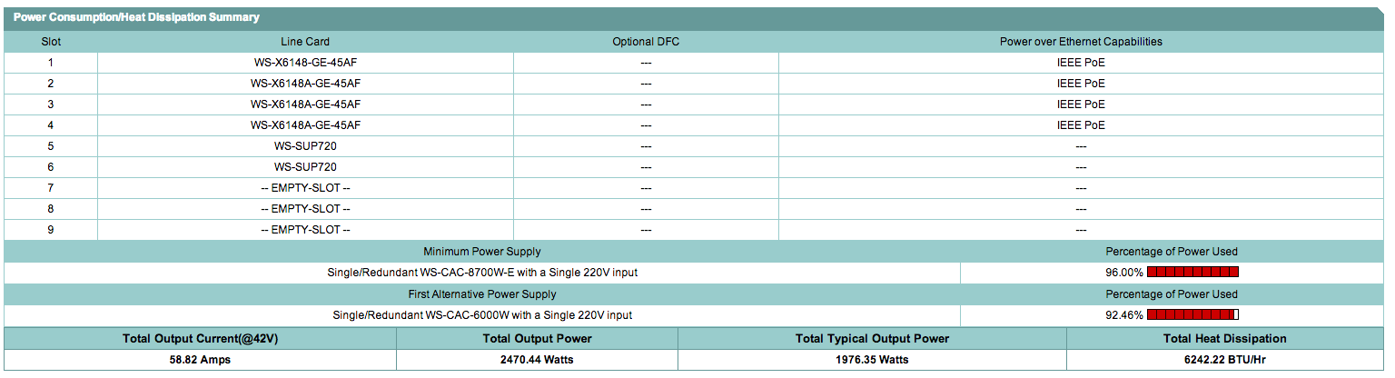
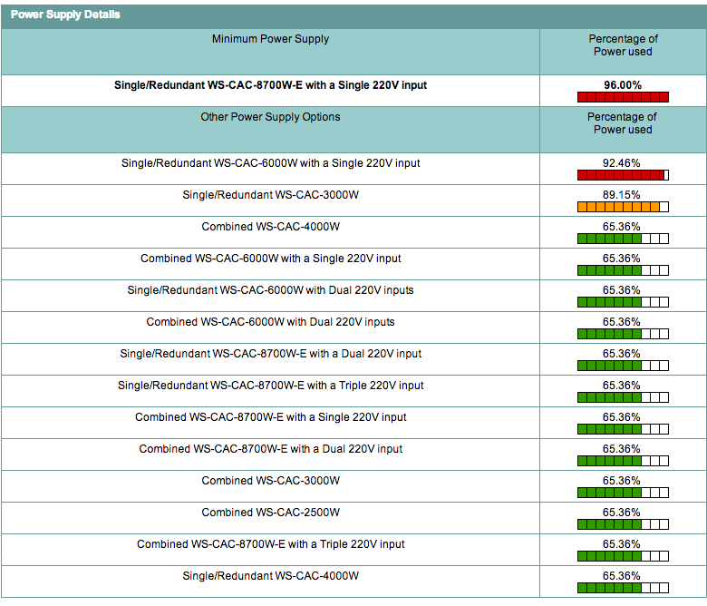
Scrolling further down the page you’ll see the calculator gives you your other power supply options. In general I recommend going for something with the green color bar(<80% utilization), as this will allow you room for future growth. The power supply you pick will depend on what you can afford, if your company has a standard power supply they use, and how many inputs (circuits/outlets) you have available in the location you will be installing the switch. One other important thing to note is the power supply mode, which I’ll cover in the next section.
Power Redundancy Modes
There are three power modes you can configure most Catalyst chassis based switches:
- Single
- Redundant
- Combined
Single
In this configuration you only have one power supply. There is no redundancy and you only have the power available from this one supply. I haven’t seen many of these deployed as people usually want redundancy, but if cost is an issue this would be the bare minimum supply you could use.
Redundant
In this configuration you will have two of the same wattage power supply installed. The total power drawn will never exceed the capability of one of the power supplies. This ensures that if a power supply were to ever fail you still have enough power remaining for the entire switch. The failover is designed to be immediate, with no downtime. The way the switch draws power from the supplies will depend on the model of the switch. As an example, the 4500 series will draw from the primary power supply only, and only use the secondary in the event of a failure. The 6500 series on the other hand will try to balance the power draw across both supplies, but still without ever exceeding the capacity of a single supply.
Combined
With this configuration you are getting the most available power for the switch, at the cost of no redundancy. The total available power will be the sum of each of the power supplies. In the event of a power supply failure, there are two scenarios:
- The total power consumed never exceeded the power supplied by a single power supply, so you will still have enough to run the switch. For example, if you have 2 x 6000 W power supplies (12000 W total in combined mode) but your power usage was only 4000W, one power supply could fail and you would still have enough (6000W).
- The total power consumed exceeded the power supplied by a single power supply. In this case the switch will need to power down linecards (usually starting from the bottom to the top, with the supervisors last) until it has enough power. For example, if you have 2 x 6000 W power supplies (12000 W total in combined mode) but your usage was 10,000 W, one power supply fails and you now only have 6000 W available. Since 8,000 W > 6000 W available, the switch can’t run as it was previously. For the 6500,the switch will start shutting off power to PoE devices in descending order, starting with the highest port on the highest numbered module. If it still doesn’t have enough power it will start powering off the line cards themselves, starting with the highest numbered. If you run a ‘show power’ command when the switch is in this state you would see power-deny listed in the Operational column for the line cards that were shutdown.
Working with your Electrician
Now that you ran the power calculator and determined which power supplies and how many inputs will be required for each you can work with your Electrician to have the correct outlets installed or verify existing outlets are adequate. There are four things your Electrician will need to know:
- Number of outlets
- Voltage for each outlet
- Max Amps for each outlet
- Outlet type
Number of outlets
Typically there will be one outlet per input of the power supply. If you have two power supplies, each with 2 inputs, you’ll need a total of four outlets installed.
Voltage for each outlet
The voltage you need will come from the output of the Power Calculator. If you ran the calculator using 100-120 V then you would tell the Electrician you need a 120V outlet, if you ran the calculator using 220 V, then you need 220V outlets. Likewise, if you are connecting this to a UPS, make sure the output of the UPS has the correct output voltage.
Amps per outlet
The Amps that each outlet will draw will depend on the power supply you select. This can usually be found in the spec sheet for the power supply on Cisco’s website under the section “Input Current (per input)”. See below for an example of a 6000W power supply that has 16A(max) per input. This is important for the Electrician so they can size the circuit connected to each outlet appropriately.

Outlet Type
There are a number of different outlet types available. The country you are installing in can affect the outlet type as can the requirement for a locking outlet vs non-locking outlet. I will write another post on the different options for outlets but the most important thing is to make sure the power cords you order with your switch will plug into the outlets the Electrician has installed. If the room has a certain type of outlet and you order a different power cord, you’ll be out of luck. Work with your distributor and the Electrician to make sure they match.
To be continued…
At this point we ran through the calculator, determined what the power requirements for our switch are, and the basics that need to be communicated to the Electrician in order to get you up and running. In the next post I’m going to go into further detail on some of the types of outlets that are common, best practices for power redundancy, determining how much cooling you will need for your switch, and some basic commands you can run to check the status of power on your switch.
