Deep dive into WCCP load balancing

Quick Overview

WCCP (Web Cache Communication Protocol) is a content routing protocol developed by Cisco that allows you to redirect traffic in real time.  A typical use case for WCCP would be if you have a proxy or load balancer that you want to redirect traffic to, all transparent to the end user(no configuration needed on browser).  Each WCCP setup has at least one WCCP client and one WCCP server where the proxy would be the client, and the Cisco switch/router would be the server. An access list on the switch/router defines which traffic should be redirected via WCCP, and which traffic should flow through as normal.  WCCP allows for easy scaling, fault tolerance, and load balancing.  The load balancing piece of WCCP gets a little involved so let’s take a look at how that works.

Masks and Buckets

In the case when you have more than one WCCP client, maybe you have two web proxies, WCCP provides built-in load balancing.  The way that WCCP determines which traffic is sent to each proxy is through the use of a Mask value that it applies to the IP addresses as they pass through the redirect on the switch or router.  Whether the mask gets applied to the source or destination IP is controlled by a setting on the WCCP client.  Where does the mask get set? It’s set on the WCCP client, for this example we’ll use a Websense proxy, which sets the default value to the hex value 0x1741.  The logical product of the mask and IP address, produces a value which will be called the bucket.  The buckets then get evenly distributed between WCCP clients, and your traffic is distributed accordingly.  Confused yet? Let’s break it down piece by piece.

Math

First let’s convert everything into binary. For this example, let’s use the source IP 192.168.100.5 and the default Websense mask of 0x1741.

Converting the IP to binary:      11000000 10101000 01100100 00000101

Converting the mask to binary: 00000000 00000000 00010111 01000001

Now let’s see how many possible buckets we can have with this mask. This is controlled purely by the number of ‘1’s in the mask.  If you take 2^number of 1 bits in mask, you will get the number of buckets available, in this case the mask has 6 bits set, so 2^6 = 64 buckets.  There are 64 possible combinations you could come up with when you logically AND any IP address with this specific mask

Let’s perform a sample logical AND.

logicaland

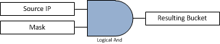
Logical AND means that any any place there is a ‘1’ in both columns of the source IP and mask, it will generate a ‘1’ in the result.  Any other combination(0 and 1, 0 and 0, 1 and 0, all equal 0).

logicalandtable

So the final result(Bucket) is 00000000 00000000 00000100 00000001, or 0x401 in hex. If you took different source IP addresses and went through the math to logically AND them together you would end up with different resulting buckets, but only 64 buckets total(2^6).  Here is the output from a Cisco switch that was connected via WCCP to two proxies(10.20.30.40 and 10.20.30.50) using the default mask 0x1741. You can see that it split up the 64 buckets into two groups (buckets 0 – 31 assigned to WCCP client ID 10.20.30.50) and (buckets 32 – 64 assigned to WCCP client ID 10.20.30.40). I added a couple comments in bold and highlighted the row where the resulting value was 0x401, from our example.

switch#show ip wccp 90 detail
WCCP Client information:
WCCP Client ID: 10.20.30.50
Protocol Version: 2.0
State: Usable
Redirection: L2
Packet Return: L2
Packets Redirected: 99
Connect Time: 1d19h
Assignment: MASK

Mask SrcAddr DstAddr SrcPort DstPort
—- ——- ——- ——- ——-
0000: 0x00001741 0x00000000 0x0000 0x0000 <——— This is our mask 0x1741, under the ‘SrcAddr’ column

Value SrcAddr DstAddr SrcPort DstPort CE-IP
—– ——- ——- ——- ——- —–
0000: 0x00000000 0x00000000 0x0000 0x0000 0x0A141E32 (10.20.30.50)
0001: 0x00000001 0x00000000 0x0000 0x0000 0x0A141E32 (10.20.30.50)
0002: 0x00000040 0x00000000 0x0000 0x0000 0x0A141E32 (10.20.30.50)
0003: 0x00000041 0x00000000 0x0000 0x0000 0x0A141E32 (10.20.30.50)
0004: 0x00000100 0x00000000 0x0000 0x0000 0x0A141E32 (10.20.30.50)
0005: 0x00000101 0x00000000 0x0000 0x0000 0x0A141E32 (10.20.30.50)
0006: 0x00000140 0x00000000 0x0000 0x0000 0x0A141E32 (10.20.30.50)
0007: 0x00000141 0x00000000 0x0000 0x0000 0x0A141E32 (10.20.30.50)
0008: 0x00000200 0x00000000 0x0000 0x0000 0x0A141E32 (10.20.30.50)
0009: 0x00000201 0x00000000 0x0000 0x0000 0x0A141E32 (10.20.30.50)
0010: 0x00000240 0x00000000 0x0000 0x0000 0x0A141E32 (10.20.30.50)
0011: 0x00000241 0x00000000 0x0000 0x0000 0x0A141E32 (10.20.30.50)
0012: 0x00000300 0x00000000 0x0000 0x0000 0x0A141E32 (10.20.30.50)
0013: 0x00000301 0x00000000 0x0000 0x0000 0x0A141E32 (10.20.30.50)
0014: 0x00000340 0x00000000 0x0000 0x0000 0x0A141E32 (10.20.30.50)
0015: 0x00000341 0x00000000 0x0000 0x0000 0x0A141E32 (10.20.30.50)
0016: 0x00000400 0x00000000 0x0000 0x0000 0x0A141E32 (10.20.30.50)
0017: 0x00000401 0x00000000 0x0000 0x0000 0x0A141E32 (10.20.30.50)
0018: 0x00000440 0x00000000 0x0000 0x0000 0x0A141E32 (10.20.30.50)
0019: 0x00000441 0x00000000 0x0000 0x0000 0x0A141E32 (10.20.30.50)
0020: 0x00000500 0x00000000 0x0000 0x0000 0x0A141E32 (10.20.30.50)
0021: 0x00000501 0x00000000 0x0000 0x0000 0x0A141E32 (10.20.30.50)
0022: 0x00000540 0x00000000 0x0000 0x0000 0x0A141E32 (10.20.30.50)
0023: 0x00000541 0x00000000 0x0000 0x0000 0x0A141E32 (10.20.30.50)
0024: 0x00000600 0x00000000 0x0000 0x0000 0x0A141E32 (10.20.30.50)
0025: 0x00000601 0x00000000 0x0000 0x0000 0x0A141E32 (10.20.30.50)
0026: 0x00000640 0x00000000 0x0000 0x0000 0x0A141E32 (10.20.30.50)
0027: 0x00000641 0x00000000 0x0000 0x0000 0x0A141E32 (10.20.30.50)
0028: 0x00000700 0x00000000 0x0000 0x0000 0x0A141E32 (10.20.30.50)
0029: 0x00000701 0x00000000 0x0000 0x0000 0x0A141E32 (10.20.30.50)
0030: 0x00000740 0x00000000 0x0000 0x0000 0x0A141E32 (10.20.30.50)
0031: 0x00000741 0x00000000 0x0000 0x0000 0x0A141E32 (10.20.30.50)

WCCP Client ID: 10.20.30.40
Protocol Version: 2.0
State: Usable
Redirection: L2
Packet Return: L2
Packets Redirected: 8
Connect Time: 1d19h
Assignment: MASK

Mask SrcAddr DstAddr SrcPort DstPort
—- ——- ——- ——- ——-
0000: 0x00001741 0x00000000 0x0000 0x0000

Value SrcAddr DstAddr SrcPort DstPort CE-IP
—– ——- ——- ——- ——- —–
0032: 0x00001000 0x00000000 0x0000 0x0000 0x0A141E28 (10.20.30.40)
0033: 0x00001001 0x00000000 0x0000 0x0000 0x0A141E28 (10.20.30.40)
0034: 0x00001040 0x00000000 0x0000 0x0000 0x0A141E28 (10.20.30.40)
0035: 0x00001041 0x00000000 0x0000 0x0000 0x0A141E28 (10.20.30.40)
0036: 0x00001100 0x00000000 0x0000 0x0000 0x0A141E28 (10.20.30.40)
0037: 0x00001101 0x00000000 0x0000 0x0000 0x0A141E28 (10.20.30.40)
0038: 0x00001140 0x00000000 0x0000 0x0000 0x0A141E28 (10.20.30.40)
0039: 0x00001141 0x00000000 0x0000 0x0000 0x0A141E28 (10.20.30.40)
0040: 0x00001200 0x00000000 0x0000 0x0000 0x0A141E28 (10.20.30.40)
0041: 0x00001201 0x00000000 0x0000 0x0000 0x0A141E28 (10.20.30.40)
0042: 0x00001240 0x00000000 0x0000 0x0000 0x0A141E28 (10.20.30.40)
0043: 0x00001241 0x00000000 0x0000 0x0000 0x0A141E28 (10.20.30.40)
0044: 0x00001300 0x00000000 0x0000 0x0000 0x0A141E28 (10.20.30.40)
0045: 0x00001301 0x00000000 0x0000 0x0000 0x0A141E28 (10.20.30.40)
0046: 0x00001340 0x00000000 0x0000 0x0000 0x0A141E28 (10.20.30.40)
0047: 0x00001341 0x00000000 0x0000 0x0000 0x0A141E28 (10.20.30.40)
0048: 0x00001400 0x00000000 0x0000 0x0000 0x0A141E28 (10.20.30.40)
0049: 0x00001401 0x00000000 0x0000 0x0000 0x0A141E28 (10.20.30.40)
0050: 0x00001440 0x00000000 0x0000 0x0000 0x0A141E28 (10.20.30.40)
0051: 0x00001441 0x00000000 0x0000 0x0000 0x0A141E28 (10.20.30.40)
0052: 0x00001500 0x00000000 0x0000 0x0000 0x0A141E28 (10.20.30.40)
0053: 0x00001501 0x00000000 0x0000 0x0000 0x0A141E28 (10.20.30.40)
0054: 0x00001540 0x00000000 0x0000 0x0000 0x0A141E28 (10.20.30.40)
0055: 0x00001541 0x00000000 0x0000 0x0000 0x0A141E28 (10.20.30.40)
0056: 0x00001600 0x00000000 0x0000 0x0000 0x0A141E28 (10.20.30.40)
0057: 0x00001601 0x00000000 0x0000 0x0000 0x0A141E28 (10.20.30.40)
0058: 0x00001640 0x00000000 0x0000 0x0000 0x0A141E28 (10.20.30.40)
0059: 0x00001641 0x00000000 0x0000 0x0000 0x0A141E28 (10.20.30.40)
0060: 0x00001700 0x00000000 0x0000 0x0000 0x0A141E28 (10.20.30.40)
0061: 0x00001701 0x00000000 0x0000 0x0000 0x0A141E28 (10.20.30.40)
0062: 0x00001740 0x00000000 0x0000 0x0000 0x0A141E28 (10.20.30.40)
0063: 0x00001741 0x00000000 0x0000 0x0000 0x0A141E28 (10.20.30.40)

Choosing the best mask

So we go through all the math, see the number of buckets, how traffic would be distributed evenly but how can we use the mask value to our advantage when deploying WCCP?  First, with the default mask it allows for 64 buckets to be distributed between only two proxies. We don’t really need all of those different buckets if we only have two WCCP clients(proxies).  If we remember from above that the number of buckets is equal to 2^number_of_bits_in_mask, then at a minimum we need only one ‘1’ bit somewhere in the mask to generate two buckets, one bucket going to proxy A and one bucket going to proxy B.  This has an added benefit on the switch by using up less of the TCAM resources.  See this link, table 3 for more info.  How you choose the best mask really depends on the type of traffic in your environment, how many proxies/WCCP clients you have, and how you want to load balance it.  Cisco recommends not using the default of 0x1741. If you have multiple sites, each one having a /16 address space, you might want to create a mask that results in each /16 getting balanced through a different proxy. If you have a single site with a number of /24 subnets you probably want to look at the third or fourth octet of the IP address so the hash is more effective(since the first two octets will always be the same a hash taking effect on those octets will be less effective at balancing traffic).  Here are a couple of examples:

  • A mask of 0x0, we end up with one bucket(2^0=1), which means there could only be one proxy, and no load balancing would take place.
  • A mask of 0x1 (00000000 00000000 00000000 00000001), we end up with two buckets (2^1=2), with even numbered last octet IP addresses going to one proxy and odd numbered last octet IP addresses going through the other proxy.
  • A mask of 0x100 (00000000 0000000 00000001 00000000), we end up with two buckets again, with even third octets going to one proxy and odd numbered third octets going to a different proxy

Cisco has a good writeup on their recommendations on the WCCP mask values for different environments available on this page. Here is an excerpt from Cisco:

  • We do not recommend using the WAAS default mask (0x1741). For data center deployments, the goal is to load balance the branch sites into the data center rather than clients or hosts. The right mask minimizes data center WAE peering and hence scales storage. For example, use 0x100 to 0x7F00 for retail data centers that have /24 branch networks. For large enterprises with a /16 per business, use 0x10000 to 0x7F0000 to load balance the businesses into the enterprise data center. In the branch office, the goal is to balance the clients that obtain their IP addresses via DHCP. DHCP generally issues client IP addresses incrementing from the lowest IP address in the subnet. To best balance DHCP assigned IP addresses with mask, use 0x1 to 0x7F to only consider the lowest order bits of the client IP address to achieve the best distribution.

Choosing a mask that works best with your environment allows you to have better control of how traffic will be distributed between proxies and makes it much more deterministic so if for example you choose 0x1 as your mask you know that any clients with even last octets are going through one proxy and all the odd last octets are going through another proxy.  During troubleshooting if you get reports that users are having issues possibly related to the proxy, by knowing what their IP ends in you can quickly correlate if all the odd numbered IPs are having an issue but even numbered IPs aren’t that Proxy A may need to be looked further.

Advertisement

Emulating WAN Throughput

When coming up with designs for different networks, I’ve found that more often than not the people from ‘the business’ or the people writing the applications put little or no thought into how their software may operate over a network.  The requirements either never get fully developed during the design phase of the project, sometimes because the application owners aren’t really sure what bandwidth or latency requirements their product needs, or it just gets left out completely.  If it works in production, it will definitely work in test right?  Sometimes it comes as an afterthought, usually when the project is already complete and in the form of ‘the network is slow and my application is perfect’. In an effort to try and get ahead of these typical scenarios there are a few options that allow you to give the application and business owners a better idea of how they can expect their product to perform *before* it is put into production and relied upon.  You can use these tools to test out anything from data file transfers to database queries to voice/video applications.


Apples to Apples

The first thing we want to do is to make sure we have as much of an apples to apples comparison as possible.  A good example of what usually happens is the application(maybe a database query for example) gets developed in a 1Gbps lab LAN environment, but when deployed gets put over your DS3 or 100Mbps WAN link between a corporate site and datacenter.  You’ve instantly changed the bandwidth(1Gbps to 10oMbps) and the latency (maybe something around 1ms in the LAN and 30ms over the WAN).  These are going to produce drastically different results, and while it shouldn’t really come as a surprise(you did change multiple variables here, right?), it often does.  It’s always better to avoid these headaches in advance if possible.  Regardless of the WAN emulation tool you end up using, the end goal should be your testing environment as close as possible to how it will be used in the real world, things like bandwidth, latency, and packet loss will all play a role.

The Tools

Depending on what OS you are running and what type of environment you have available to you, you have some options. I’ll run through some of the common ones I’ve used, and the more popular ones out there, but this is by no means an extensive list.  The ones that I am going to run through are all free, but there are a number of paid versions out there as well.

For the PC

Akmalabs makes a program called Network Simulator that runs on Windows. Once installed you define flows of traffic you want to apply the WAN emulation to, and then specify parameters like bandwidth,latency,packet loss,etc.  Any traffic that doesn’t match one of your defined flows will be unaffected by the WAN emulation. In the screenshot below I defined a flow where the source was any IP, and my destination was a computer in the same subnet as the test machine.  For the sake of the example, let’s assume you were opening up a new location somewhere in Asia that would have a 2Mbps circuit, and you knew that the latency was about 250ms round trip.  Before launching the site you wanted to test some application on your local network to see how it would perform once it is in Asia.  I set the remote IP and host mask, set a speed of 2Mbps, and 125ms delay in each direction, then clicked Save.

Akma

This next screenshot shows me pinging from the test machine(Running Network Simulator) to the test IP 10.20.9.11.  You can notice that in the beginning of the ping the response times are <1 ms since it is on a 1Gb network.  Once I clicked the ‘Save Flow’ button on the Network Simulator the RTT jump to around 250ms.

Akma pings


Here’s one more example. In this example I’ll test going to Cisco.com in a browser without any WAN emulation applied, and then I will apply some WAN emulation that makes the connection speed 128Kbps. In both examples I’m using HTTPWatch to test how long it takes to completely load the page.  In this screenshot you see the normal load time is 5.352 seconds.

Cisco-normal


I then start up Network Simulator and set the appropriate settings.

Akma-Cisco128K

And here is the HTTPWatch noticeably slower time for loading Cisco.com after the WAN emulation is applied:

Cisco-128K


For Linux/VMs

If you don’t want to install software to your computer, one of the more popular free WAN Emulators is the open source WANEM.  It is well documented and there are a number of other blog articles written on it’s different features.  WANEM comes in the form of a bootable ISO based on Linux that you could startup in any spare laptop you have lying around. If you don’t have a separate computer to dedicate to this you could also install VirtualBox and load up either the bootable ISO or if you have VMWare you could grab the Virtual Appliance they offer. Once it’s up and running there is a web GUI you can access to set all of the parameters.  In this example I had VirtualBox running the bootable ISO on my machine in ‘bridged mode’ networking so it grabbed a real address via DHCP on my network.  There are multiple ways you can send traffic to WANEM, all of which are covered in the documentation so I won’t go into much detail.  In this example I defined a route on my Windows machine sending all traffic for a test IP address to the WANEM IP address.  Alternatively you could define a route on your machine to send ALL traffic to WANEM. It all depends on what you are testing.  When adding the routes in Windows you need admin rights(‘Run as Administrator’ for a cmd prompt). For my example I added a route for a specific host like this, where 4.2.2.2 is the destination address and 10.20.239.28 is the IP address of the WANEM software in my VirtualBox:

wanem-routeadd


Once WANEM is running you can browse to it in a web browser and start set the parameters.  One cool thing you can do is use their ‘WANalyzer’ which will let you enter in a test IP address and evaluate the network between WANEM and the test IP to determine stuff like the speed, delay, and jitter. You then can apply these settings directly to any of the traffic you are testing in the emulator.  This is good if you aren’t sure about what your network conditions are like and can be a good place to start. I would use this with caution and check the results to see if they are what you would expect. If you know all of the settings already, then you can skip this part.  This is what the results look like for the WANalyzer to a test IP:

wanem-Wanalyzer


I ended up ignoring the settings from WANalzyer and just ended up setting my own, defining a delay of 100ms:

wanem-settings


Performing a ping to the test IP 4.2.2.2 shows RTT around 100ms:

wanem-100msping

When you are done testing, make sure you delete any routes you added to your test machines.  If you don’t you’ll just end up pulling your hair out later on when you are getting poor performance or something isn’t working correctly:

wanem-routedelete

For the MAC

If you are on a MAC and don’t feel like installing anything, good news, you have a WAN emulation software already built in.  This takes advantage of the built-in ‘ipfw’ app.  There are two parts to setting this up, the first involves creating pipes that define the source and destination of the traffic you want to send through the WAN emulator, and the second involves configuring the pipes for things like bandwidth, latency, and packet loss.

Here’s the first part, I’ll define the traffic I want to send through the WAN emulation  In this case I’ll pick traffic going to Google’s public DNS 8.8.8.8:


sudo ipfw add pipe 1 ip from any to 8.8.8.8

sudo ipfw add pipe 1 ip from 8.8.8.8 to any


Next I’ll add in the delay for that pipe.  In this case, we will add in 75ms delay.  Besides delay you can also set the speed and packet loss. The syntax is:

sudo ipfw pipe 1 config delay [delay] bw [bandwidth] plr [packetloss_as_decimal]


For mine i used:

sudo ipfw pipe 1 config delay 75ms

sudo ipfw pipe 2 config delay 75ms

And here is the output of a ping:

-iMac:~ Joe$ ping 8.8.8.8

PING 8.8.8.8 (8.8.8.8): 56 data bytes

64 bytes from 8.8.8.8: icmp_seq=0 ttl=45 time=176.715 ms

64 bytes from 8.8.8.8: icmp_seq=1 ttl=45 time=176.334 ms

64 bytes from 8.8.8.8: icmp_seq=2 ttl=45 time=175.636 ms

64 bytes from 8.8.8.8: icmp_seq=3 ttl=45 time=187.775 ms


This is ~175ms, 75ms in each direction, plus around 25ms of normal RTT without the ipfw rules.


When you are done testing, make sure to delete the rules or flush them out:

sudo ipfw -q flush


Wrap Up

So that’s it, I’d encourage you to play with some or all of these tools and get familiar with them.  Whether you just want to learn how different network conditions can impact applications or you have a real project you want to test out, they are very useful.  There are some limitations as to the conditions you can test with each of the tools, so read through some of the documentation first to make sure they will yield accurate results for your test scenarios.  If you are looking to test something beyond what the free versions can offer you can look to some of the paid versions of software that are out there.  Hope this was helpful.

Automation: Making Better networks

As part of the same project I wrote this python script for, I created an Excel/VBA script to allow our team to quickly and consistently input all of the data required for the VPN hardware we were shipping out to over 450 locations.  The output of this Excel spreadsheet would later serve as the input to the Python script I wrote, and combined they are working out very well.

Why Bother?

Before I dive into the Excel/VBA code I’d like to give a little bit of background on my thoughts on why this was worth getting into.  From my experience, it’s fairly easy to come up with the configuration for a single site, or even a couple of sites.  You have the time to verify everything is correct, put everything in by hand, and really dedicate the time to check everything is how you want it.  This gets more difficult as you scale in size.  Even at 10 or 20 sites you start to increase your margin of error for a typo here or there, or you might run out of time and not be able to check everything as well as you would like.  Once you start to get into hundreds of devices to configure it makes things that much more complex.  It’s now very difficult, if not impossible, for a single person to manually configure each location and requires a very large amount of time dedicated to a single project.  If you take the time to automate a process, whether it is with a script, Excel, or some other combination of tools you can reduce the number of human errors as well as reduce the time and resources that would otherwise need to be dedicated to the project.

The problem

The project that led to this particular Excel VBA script required shipping out VPN hardware to over 450 locations.  Each VPN appliance was shipped to us by the carrier and was already assigned to a specific site.  There were a few different unique pieces of information, all in different spreadsheets that all needed to be tied together:

  1. Spreadsheet including Site ID and MAC address of VPN appliance
  2. Spreadsheet including Public IP address information from various broadband providers
  3. Spreadsheet including Internal IP addresses and identifying the type of configuration each site would get

The different types of configurations for each site were important as they dictated what equipment and information would need to be set up for each site.  The three options were:

  1. Broadband as a primary connection with a cellular USB as the backup
  2. Combination of broadband and T1
  3. T1 with cellular backup

If you had a site that fell under ‘option 1’ then it required entering in the public IP address information for that site, as well as keeping track of the cellular SIM ICCID and IMEI numbers.  If you had a site that was under ‘option 2’ you would only enter in the public broadband IP address, but would not need to package any cellular USB sticks.  If you had a site with ‘option 3’ then you would not have any broadband IP information to enter, but would need to package a cellular USB stick and record that information down.

Doing any of the above manually would be very labor intensive, flipping between multiple spreadsheets to check the type of setup the site would have, figure out which information to record and ship out. So, we automate.

VBA

Prior to this project I hadn’t written a VBA script since middle school.  I ended up having to re-learn a number of things to write this script but in the end it was worth it.  It has a lot of similarity to a pivot table, with some added extras.  The idea behind the script is this:

  • Every VPN hardware appliance has a barcode on the box that includes the MAC address of the device.  We can use a barcode scanner to scan that box and do a lookup of the MAC address in Spreadsheet #1 which will give us the site ID we are working with.
  • Then do another lookup of that site ID in another spreadsheet and pull the type of configuration(Broadband,Cellular,T1 combinations)
  • Prompt the user for the appropriate required information, depending on which type of configuration the site will get.  For example, if the site will need Broadband and cellular, then display the fields for broadband IP address and cellular information.  If the site will be getting a T1 with cell backup, don’t prompt the user for any broadband information.
  • At the end of the script, tell the user which instructions to package with the device before it gets shipped out.

Some screenshots

Here’s some screenshots of what the tool looks like when run with a Broadband/Cell Site:

1) Start off by scanning the barcode of the VPN Appliance

Image

2)Prompt the user for the appropriate information so it can be saved to a database.

Detected this was a broadband/cellular site. Prompt the user for the appropriate information.

Detected this was a broadband/cellular site. Prompt the user for the appropriate information.

3)Present the user with all of the necessary information for that store so they can enter it into the VPN gateway.

Present the Broadband IP address information to the user for this specific site so they can enter it into the VPN hardware appliance.

Present the Broadband IP address information to the user for this specific site so they can enter it into the VPN hardware appliance.

Excel IP Functions

I was working on a project the other day where I had a list of ~ 500 /30 subnets in Excel that I needed to break out so each host in the /30 was in it’s own column.  Seemed pretty straight forward, but there was no built in function to handle this.  With all of the other math functions Excel has built in, you would think that in 2014 some functions that deal with IP addresses would be standard.  Guess not.  Rather than spend the time to write one from scratch, a quick Google search came up with an entire set of functions written by Rajeev Bhardwaj. He put together an excellent presentation that shows the usage of each of the functions located here:   http://www.slideshare.net/rajivss/ip-functions-presentationgen-v11 .  This not only helped me solve my current problem but all of the other tools included in the Add-In will definitely get used in the future.

Here’s a quick summary of the included tools:

  • IP_Bits2Mask – Converts the number of bits from a / notation to an expanded subnet mask
  • IP_ErrChk – Checks to see if a value is a valid IP address or not
  • IP_Hosts – Calculates the number of hosts from a specific subnet mask
  • IP_IP2Mbits – Calculates the subnet mask required to obtain a certain number of host addresses
  • IP_Mod – Takes any octet of the IP address and increments/decrements it by the set value
  • IP_NextSub – Calculates the next subnet
  • IP_Bcast – Calculates the broadcast address for a given IP
  • IP_Count – Counts the occurrence of an IP in a range of subnets
  • IP_IsExist – Check if an IP address exists in a subnet
  • IP_Mask2Bits – Calculates the mask bits from a subnet mask in dotted notation
  • IP_Subnet – Calculates the subnet address for a given host IP

I would recommend you visit Rajeev’s site and download the Excel add-in to be able to take advantage of all these functions.  You can visit his site to download the tools here: http://rajivbhardwaj.com/download/


Determining Power and Cooling requirements for the Cisco Catalyst (Part 2)

More Power

In the last post I went over determining how much power your Cisco Switch is going to need to run, options for power supply redundancy, and what information your electrician will need to make all of this happen.  This post will expand on that a little more and go over the types of outlets available, building in some resiliency to your electrical design and determining your cooling needs.

Outlets

The type of outlet you choose will be decided by the number of volts required, country you are in, and available cords/plugs from the manufacturer.  I can’t cover every possible receptacle across the world so I’m going to focus on common receptacles in the US when installing network equipment.

NEMA

NEMA (National Electrical Manufacturers Association) is a group that develops standards for electrical manufacturers.  A small piece of what they cover includes the plugs and receptacles used throughout North America.  Plugs and receptacles can be sorted into two broad categories : straight-blade and locking.  Straight blade plugs/receptacles are seen on the majority of general use electrical devices while locking plugs/receptacles are seen more in commercial settings where the locking plug helps prevent accidental disconnection.  For single RU or stackable switches it is common to see a straight-blade plug.  In the chassis based switches and in the datacenter I prefer the locking style plugs and receptacles.  You could use a straight-blade plug or twist-lock plug on either type of switch, a lot of it comes down to preference and what is more common/available. The naming convention for NEMA plugs and receptacles is pretty straight forward. Here’s a diagram I made to help.

NEMA Nomenclature

The common NEMA outlets seen for networking equipment are in the table below:

CommonOutletsNote: L5-20R and L6-30R plugs/outlets look similar, but are not.  It is normally imprinted on the plug and receptacle.

Levels of Redundancy

Designing your switch with redundant power supplies is only one piece of the bigger redundancy picture.  If you don’t fully think through how power is being supplied to your switch you might run into some unexpected outages down the line.  How redundant you go depends a lot on your requirements.  If this is a core switch in a mission critical environment you would probably want to look into a generator, UPS and multiple electrical feeds.  If this is an access-layer switch servicing end users, you may want a UPS, redundant power feeds, or both.  If you don’t think you need any redundancy, you might not even include a UPS (this should be the rare case, always get a UPS when possible).  The more redundancy you add in, the more money you can expect to spend.  Let’s look at a few examples, going from least redundant to most redundant.

Utility Power (Single circuit, Single Power Supply)

power_red1

In this example we have a single power supply in the switch, being serviced by a single outlet.  If we lose power from the outlet or the power supply dies, there will be an outage.

Utility Power (Single Circuit, Dual Power Supplies)

power_red2

In this example we have dual power supplies, each being fed from a separate outlet.  In this case we can tolerate a single power supply failure and still be up, however we have a single point of failure at the power panel since both of these outlets are fed from the same panel and same circuit.  If the power panel has an issue(the single breaker trips for example), the entire switch would be down, regardless of the redundant power supplies.

Utility Power(Dual Circuits, Dual Power Supplies)

power_red3

This shows dual power supplies, each being fed from a separate outlet, and each outlet is fed with a dedicated circuit.  Here we can tolerate a single power supply failure, as well as one of the two dedicated circuit breakers tripping.  If you need redundancy but aren’t getting a UPS for some reason(again, you should be getting a UPS), this would be the design I would want to go with.

UPS(Dual Power Supplies)

power_red4This starts to provide us some more resiliency. We still have redundant power supplies in the event that one dies.  We’re no longer relying on just the utility power to keep the switch up.  We add in a UPS which will give us an additional runtime should the utility power go down for a short time.  It’s important to note that the UPS generally isn’t meant to provide long term back up power.  Usually it is designed to handle short term failures, and while you can add additional batteries it starts to become costly.   The UPS does end up being a single point of failure, bringing us to the next scenario.

Dual UPS(Dual Power Supplies)

power_red5

This provides the same redundancy as the previous example, but adds in an additional UPS, eliminating the UPS as the single point of failure.

Generator, UPS, Dual Power Supplies

power_red6This is the last example I’ll go into, providing the most redundancy so far.  In this case you have Utility power and a generator feeding an Auto Transfer Switch(ATS).  The ATS will switch to generator power if it detects the loss of utility power.  This feeds a UPS which provides cleaner power to the end networking or server equipment.  The UPS also allows you to keep the network switch up in the time it takes the generator to start up and provide electricity.  You would see this setup in the datacenter or environments that can’t tolerate any downtime.

And so on….

There are probably an infinite amount of redundant power configurations I could go into.  This shows the more common ones that I’ve run across, but is definitely not every one out there( you could have two separate utilities feed power, multiple generators, etc).  The main point I hope this gets across is that just having redundant power supplies in your piece of equipment doesn’t mean much unless you consider all of the components that come before electricity makes it to your switch.


Determining Power and Cooling requirements for the Cisco Catalyst (Part 1)

Speaking with a coworker the other day it dawned on me that there are a number of areas of networking that just aren’t covered as part of the ‘normal’ course of learning.  Things like IGPs,EGPs, spanning tree, FHRPs, and access lists are covered in depth and can be found everywhere from books to blogs to week long training classes.  Then there’s ‘the other stuff’ – Best practices for cabling, UPS design, monitoring, scripting, and power and cooling, just to name a few. The stuff that isn’t documented as well but is still an absolute necessity for most people at some point in their network engineering career.  In the next few blog posts I’m going to run through the basic design process for the power and cooling of your switches.

Power Basics

Before we can jump into determining the power requirements for your switch we need to gain a basic understanding of how power is calculated.  The formula to calculate power is P = VI, or spelled out: Power = Voltage x Current. Power is measured in watts, usually abbreviated by W, Voltage measured in volts abbreviated by V, and Current is measured in Amps, abbreviated by A.

A common analogy that is often used to explain each of the terms is that of a garden hose or plumbing system.  In this analogy the Voltage is equivalent to the pressure in the system, the Current is equivalent to the rate of flow, and the Wattage is the total amount of water that comes out of the hose or pipe.  Let’s say you need to fill up a swimming pool using the hose.  We can turn the water on using the normal faucet and it will fill slowly (low pressure), or if we used some type of external pump we could fill the pool quickly (high pressure).  Similarly, if the network switch we are working with needs more watts(maybe you have PoE line cards with attached phones you need to power), we can increase the voltage which will generate more watts.  For more details on the basic power formula or the water analogy check out this site.

Calculating Power Requirements

At some point in buying the new switch you’ll need to provide the power requirements to someone like an Electrician to make sure you have enough power to run the switch.  Every linecard, supervisor, and PoE device you put into your switch will have some power draw and you need to make sure you have enough power available.  If you’re working with a switch in the Cisco Catalyst(and Nexus 7K) line, they have a very useful tool called the Cisco Power Calculator (Free,CCO Login Required) that lets you build your switch with specific linecards and will output the power and cooling requirements.  Let’s take a look.

After you launch the tool you select the product family from the dropdown.

CPC - Switch Selection

After selecting the product family, you start to populate the switch with the specific chassis model, supervisor, redundant supervisor if applicable, and input voltage.  For input voltage, we have four choices. The first two choices, -48 Volts DC and -60 Volts DC  are used if you’ll be connecting this directly to a battery as the source.  DC voltage  is popular for phone system/telecom equipment as it doesn’t introduce noise (audible hum) into the line like AC would, and provides assurance against power outages.  Bonus fact: The DC voltage is negative to reduce corrosion. The second two options in the dropdown are 100 – 120 Volts and 200 – 240 Volts.  Every deployment of a Cisco switch I’ve done so far has used AC power to supply the switch, either straight from a wall outlet or outputted from a UPS, and the example I’ll run through will use AC voltage.  How do you know which AC voltage you should pick?  There are a couple factors:

  • Country you are deploying the switch in. Some countries have a standard voltage of 100-120 Volts and some countries have a standard of 200-240 Volts.  Find out what voltage is standard in the country the switch will be installed and choose accordingly.  Note that these are the standard voltages, but there may be other options (for example, while 110 Volts is common in houses in the US, it is not uncommon to have 220V circuits installed in offices, datacenters, or other locations that may need additional power). Work with your electrician.
  • Existing electrical wiring or new electrical wiring.  If you are installing this switch and need to utilize the existing outlets or UPS, you can work with the electrician or building management to determine what voltage you have available to you.  If it is a brand new install and you have the ability to tell the electrician what to install, then you can run through the Cisco Power calculator using both voltages (if available in your country) and see which works better for you.

For this example I’m going to select 200-240 Volts, as that’s what I’ve typically worked with for the bigger chassis based switches with multiple linecards.  I also selected redundant Sup720s.

On the next page you can select which linecard will go in each slot.  If you select a PoE linecard it will ask you to specify the number and type of PoE devices attached to that linecard.  It’s important to keep in mind what your future growth may look like.  For example, if you only will have two PoE linecards today, each partially filled with some PoE devices, you may be able to get away with a small power supply and a lower voltage circuit from your electrician today.  If you know that you will be expanding sometime in the near future, it’s much easier to get the bigger power supply and have your electrician wire the electrical circuit appropriately now, then need to revisit this in 6 months or a year when the electrician needs to install all new circuits and you need to buy bigger power supplies.  Each situation will be different so there is no one size fits all, use your judgement.

I’m going to populate this chassis with 4 PoE linecards and tell the wizard that I’ll be connecting 96 Cisco 7941-G-GE phones. The calculator knows the power draw for every PoE device(phones, access points, etc) in the list so you just need to know how many of each you have now (or will have in the future) and give it some good estimate.

Phones

Now we’re ready to look at the results. There’s a lot going on in this page but it’s not that bad if you break it down. The top sections show you how you’ve configured your switch and the MINIMUM power supply and number of power inputs you could get away with to adequately power this switch and connected devices.  It’s important to note the number of inputs. Most of the bigger power supplies may offer the option for multiple inputs.  This is good in that it allows you to supply more power to the switch, but you’ll need to keep in mind that for every additional input into the power supply it means an additional circuit/outlet that your electrician will need to install if this is a new install, or that you would need to already have available if it will be utilizing existing outlets.  The “Percentage Used” section with colored meter will show you what percent of the listed power supply you will be using from the start.  You typically would want to include room for growth.  In my example, if we chose the minimum power 8700 Watt power supply with a single 220 Volt input, we would already be at 96% utilization.  If I’m asked to install an additional line card a few months from now, we will need additional power, most likely in the form of an additional electrical circuit/input.

CPC - Results

Scrolling further down the page you’ll see the calculator gives you your other power supply options.  In general I recommend going for something with the green color bar(<80% utilization), as this will allow you room for future growth.  The power supply you pick will depend on what you can afford, if your company has a standard power supply they use, and how many inputs (circuits/outlets) you have available in the location you will be installing the switch. One other important thing to note is the power supply mode, which I’ll cover in the next section.

CPC - Results 2

Power Redundancy Modes

There are three power modes you can configure most Catalyst chassis based switches:

  • Single
  • Redundant
  • Combined

Single

In this configuration you only have one power supply.  There is no redundancy and you only have the power available from this one supply. I haven’t seen many of these deployed as people usually want redundancy, but if cost is an issue this would be the bare minimum supply you could use.

Redundant

In this configuration you will have two of the same wattage power supply installed.  The total power drawn will never exceed the capability of one of the power supplies.  This ensures that if a power supply were to ever fail you still have enough power remaining for the entire switch.  The failover is designed to be immediate, with no downtime. The way the switch draws power from the supplies will depend on the model of the switch. As an example, the 4500 series will draw from the primary power supply only, and only use the secondary in the event of a failure.  The 6500 series on the other hand will try to balance the power draw across both supplies, but still without ever exceeding the capacity of a single supply.

Combined

With this configuration you are getting the most available power for the switch, at the cost of no redundancy.  The total available power will be the sum of each of the power supplies.  In the event of a power supply failure, there are two scenarios:

  1. The total power consumed never exceeded the power supplied by a single power supply, so you will still have enough to run the switch.  For example, if you have 2 x 6000 W power supplies (12000 W total in combined mode) but your power usage was only 4000W, one power supply could fail and you would still have enough (6000W).
  2. The total power consumed exceeded the power supplied by a single power supply. In this case the switch will need to power down linecards (usually starting from the bottom to the top, with the supervisors last) until it has enough power.  For example, if you have 2 x 6000 W power supplies (12000 W total in combined mode) but your usage was 10,000 W, one power supply fails and you now only have 6000 W available.  Since 8,000 W  > 6000 W available, the switch can’t run as it was previously.  For the 6500,the switch will start shutting off power to PoE devices in descending order, starting with the highest port on the highest numbered module.  If it still doesn’t have enough power it will start powering off the line cards themselves, starting with the highest numbered.  If you run a ‘show power’ command when the switch is in this state you would see power-deny listed in the Operational column for the line cards that were shutdown.

Working with your Electrician

Now that you ran the power calculator and determined which power supplies and how many inputs will be required for each you can work with your Electrician to have the correct outlets installed or verify existing outlets are adequate.  There are four things your Electrician will need to know:

  1. Number of outlets
  2. Voltage for each outlet
  3. Max Amps for each outlet
  4. Outlet type

Number of outlets

Typically there will be one outlet per input of the power supply.  If you have two power supplies, each with 2 inputs, you’ll need a total of four outlets installed.

Voltage for each outlet

The voltage you need will come from the output of the Power Calculator.  If you ran the calculator using 100-120 V then you would tell the Electrician you need a 120V outlet, if you ran the calculator using 220 V, then you need 220V outlets.  Likewise, if you are connecting this to a UPS, make sure the output of the UPS has the correct output voltage.

Amps per outlet

The Amps that each outlet will draw will depend on the power supply you select.  This can usually be found in the spec sheet for the power supply on Cisco’s website under the section “Input Current (per input)”.  See below for an example of a 6000W power supply that has 16A(max) per input.  This is important for the Electrician so they can size the circuit connected to each outlet appropriately.

Input Current

Outlet Type

There are a number of different outlet types available.  The country you are installing in can affect the outlet type as can the requirement for a locking outlet vs non-locking outlet.  I will write another post on the different options for outlets but the most important thing is to make sure the power cords you order with your switch will plug into the outlets the Electrician has installed.  If the room has a certain type of outlet and you order a different power cord, you’ll be out of luck.  Work with your distributor and the Electrician to make sure they match.


To be continued…

At this point we ran through the calculator, determined what the power requirements for our switch are, and the basics that need to be communicated to the Electrician in order to get you up and running.  In the next post I’m going to go into further detail on some of the types of outlets that are common, best practices for power redundancy, determining how much cooling you will need for your switch, and some basic commands you can run to check the status of power on your switch.

Monitoring HSRP Failover with EEM

Background

We’re currently using Solarwinds to monitor our network infrastructure. While it does a decent job at monitoring the basics, there are certain things I feel it could do better right out of the box.  I have this preconceived idea of what the ideal NMS should have, looking at your config and then strongly recommending what you should monitor based on what it finds.  Unfortunately I haven’t found that yet.  Solarwinds is great if you want the pretty GUI, NAGIOS is very powerful if you know what you want to monitor and don’t mind a little scripting, but theres nothing I’ve found (yet) that does it all the way I want.  One of the things I think are important is tracking your HSRP failover events.  In a typical old school (no VSS or other newer technologies) redundant environment you would have two switches running HSRP between them, where one takes over if the other fails.  It’s possible you could go months or years without monitoring HSRP without any issues. It’s also possible you could be having constant HSRP events happening that you never even see unless you are specifically looking for them.  These could cause brief interruptions to your user traffic depending on how your timers are tuned, and probably just get reported as general ‘the network is slow/horrible/never works/etc’. To monitor these events without getting too deep into Solarwinds or other monitoring solutions I decided to turn to EEM.

EEM

EEM is a pretty powerful and flexible component of IOS/NX-OS that allows you to track or alert on certain events on Cisco devices.  I won’t go into all of the features that EEM has as it is well documented.  If you are interested in finding out more about EEM I’d recommend looking through Cisco’s site, starting here: https://supportforums.cisco.com/docs/DOC-27996.

HSRP Applet

The applet we are going to write is referred to as a syslog collector script.  It simply monitors the syslog messages that are generated by the router/switch and performs some action based upon the detection of a certain string.Basic, but powerful. Here’s the script I created:

ip name-server 1.2.3.4

event manager environment _mail_smtp smtp.yourcompany.com

event manager environment _mail_rcpt networkteamdistro@yourcompany.com

event manager session cli username “yourusername”

event manager applet HSRPEvent

event syslog pattern “HSRP-5-STATECHANGE”

action 1.0 info type routername

action 2.0 mail server “$_mail_smtp” to “$_mail_rcpt” from “fromemail@yourcompany.com” subject “HSRP State Change on $_info_routername” body “$_syslog_msg”

Some notes on what the script is doing:

  • ip name-server– Required if you are using a DNS name for your SMTP server.
  • event manager environment – both of these lines are setting variables _mail_smtp and _mail_rcpt, which are used later in the script to send mail
  • event manager session cli username – used to set the username you want to run the script as. You do not need a password. IOS uses the username only for authorization purposes, not actual authentication. It will check the authorization locally or against a AAA server like ACS.
  • event syslog pattern – is telling the applet to search the syslogs for the specified pattern
  • action 1.0 info type routername – just stores the router’s current router’s name into a variable.  This is useful so when I get the email I’ll know which switch it’s coming from
  • action 2.0 – Is sending an email using some of the variables from above. The subject has the text “HSRP State Change on <ROUTERNAME>”. The body will contain the actual Syslog text, which will contain the state change.  As an example, the body of the text would look something like this: “3348414: Jan 27 13:51:19.687 EST: %HSRP-5-STATECHANGE: Vlan181 Grp 181 state Standby -> Active”

The Big Picture

This applet is just one small example of what you can do with EEM.  The possibilities are nearly endless.  While this focuses on one specific aspect of the network, I think it’s important to always be looking at your own network and seeing how you can improve, both in the network itself and in monitoring the network.  ‘Ignorance is bliss’ doesn’t really apply to networking.  Problems will eventually catch up to you, usually snowballing into some type of bigger issue and it’s always better to get ahead of them early on.  Monitoring is a big part of that and EEM is a quick way to achieve it.  What type of EEM applets have you found to be useful?