More Power
In the last post I went over determining how much power your Cisco Switch is going to need to run, options for power supply redundancy, and what information your electrician will need to make all of this happen. This post will expand on that a little more and go over the types of outlets available, building in some resiliency to your electrical design and determining your cooling needs.
Outlets
The type of outlet you choose will be decided by the number of volts required, country you are in, and available cords/plugs from the manufacturer. I can’t cover every possible receptacle across the world so I’m going to focus on common receptacles in the US when installing network equipment.
NEMA
NEMA (National Electrical Manufacturers Association) is a group that develops standards for electrical manufacturers. A small piece of what they cover includes the plugs and receptacles used throughout North America. Plugs and receptacles can be sorted into two broad categories : straight-blade and locking. Straight blade plugs/receptacles are seen on the majority of general use electrical devices while locking plugs/receptacles are seen more in commercial settings where the locking plug helps prevent accidental disconnection. For single RU or stackable switches it is common to see a straight-blade plug. In the chassis based switches and in the datacenter I prefer the locking style plugs and receptacles. You could use a straight-blade plug or twist-lock plug on either type of switch, a lot of it comes down to preference and what is more common/available. The naming convention for NEMA plugs and receptacles is pretty straight forward. Here’s a diagram I made to help.

The common NEMA outlets seen for networking equipment are in the table below:
 Note: L5-20R and L6-30R plugs/outlets look similar, but are not. It is normally imprinted on the plug and receptacle.
Levels of Redundancy
Designing your switch with redundant power supplies is only one piece of the bigger redundancy picture. If you don’t fully think through how power is being supplied to your switch you might run into some unexpected outages down the line. How redundant you go depends a lot on your requirements. If this is a core switch in a mission critical environment you would probably want to look into a generator, UPS and multiple electrical feeds. If this is an access-layer switch servicing end users, you may want a UPS, redundant power feeds, or both. If you don’t think you need any redundancy, you might not even include a UPS (this should be the rare case, always get a UPS when possible). The more redundancy you add in, the more money you can expect to spend. Let’s look at a few examples, going from least redundant to most redundant.
Utility Power (Single circuit, Single Power Supply)

In this example we have a single power supply in the switch, being serviced by a single outlet. If we lose power from the outlet or the power supply dies, there will be an outage.
Utility Power (Single Circuit, Dual Power Supplies)
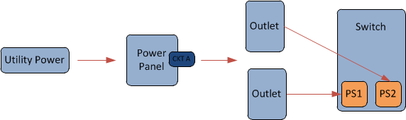
In this example we have dual power supplies, each being fed from a separate outlet. In this case we can tolerate a single power supply failure and still be up, however we have a single point of failure at the power panel since both of these outlets are fed from the same panel and same circuit. If the power panel has an issue(the single breaker trips for example), the entire switch would be down, regardless of the redundant power supplies.
Utility Power(Dual Circuits, Dual Power Supplies)

This shows dual power supplies, each being fed from a separate outlet, and each outlet is fed with a dedicated circuit. Here we can tolerate a single power supply failure, as well as one of the two dedicated circuit breakers tripping. If you need redundancy but aren’t getting a UPS for some reason(again, you should be getting a UPS), this would be the design I would want to go with.
UPS(Dual Power Supplies)
 This starts to provide us some more resiliency. We still have redundant power supplies in the event that one dies. We’re no longer relying on just the utility power to keep the switch up. We add in a UPS which will give us an additional runtime should the utility power go down for a short time. It’s important to note that the UPS generally isn’t meant to provide long term back up power. Usually it is designed to handle short term failures, and while you can add additional batteries it starts to become costly. The UPS does end up being a single point of failure, bringing us to the next scenario.
Dual UPS(Dual Power Supplies)

This provides the same redundancy as the previous example, but adds in an additional UPS, eliminating the UPS as the single point of failure.
Generator, UPS, Dual Power Supplies
 This is the last example I’ll go into, providing the most redundancy so far. In this case you have Utility power and a generator feeding an Auto Transfer Switch(ATS). The ATS will switch to generator power if it detects the loss of utility power. This feeds a UPS which provides cleaner power to the end networking or server equipment. The UPS also allows you to keep the network switch up in the time it takes the generator to start up and provide electricity. You would see this setup in the datacenter or environments that can’t tolerate any downtime.
And so on….
There are probably an infinite amount of redundant power configurations I could go into. This shows the more common ones that I’ve run across, but is definitely not every one out there( you could have two separate utilities feed power, multiple generators, etc). The main point I hope this gets across is that just having redundant power supplies in your piece of equipment doesn’t mean much unless you consider all of the components that come before electricity makes it to your switch.
